CPET 491 / PURDUE UNIVERSITY FORT WAYNE
From detection
to response.
An IoT fire detection and automatic suppression prototype, built by a three-person senior design team. I led system architecture and firmware development, connecting sensor readings to local alerts, mechanical actuation, and remote notifications.
Watch the demonstration ↓- Average detection time
- ≈ 1.48s
- Detection trials under 2 seconds
- 6 / 6
- Active requirements verified
- 17 / 17
- Final prototype cost
- $366.38
01 / THE CHALLENGE
Connect the whole response.
The project explored how a compact system could detect a potential fire, warn people nearby, send a remote alert, and activate a suppression mechanism. The challenge was integrating those functions into one working prototype for small indoor environments.
This was an academic proof of concept tested in controlled conditions. It was not certified for commercial fire protection or intended to replace a certified system.
02 / MY CONTRIBUTION
Architecture and firmware.
I designed the system structure and developed the ESP32 firmware in C/C++ using the Arduino framework. I evaluated MQTT as a communication option and implemented Twilio SMS alerts through HTTP POST requests over Wi-Fi.
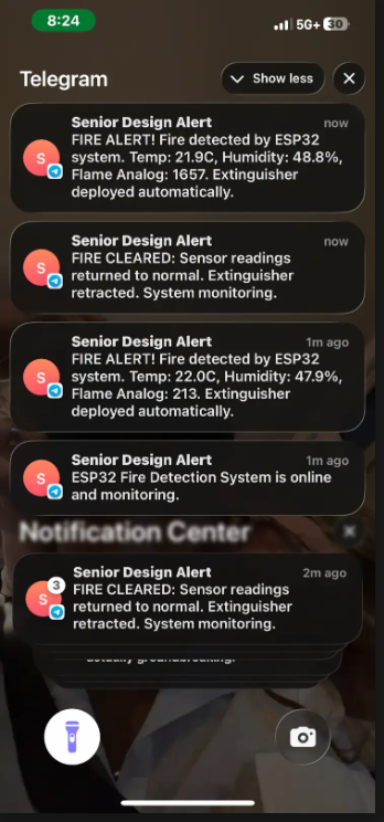
The firmware brought together sensor input, detection logic, relay control, alerts, and automatic reset. I also contributed to project documentation and software reporting. I also integrated Telegram notifications, shown in the demonstration gallery.
Team contributions: Max Tsenov focused on component selection, sensor integration, and hardware testing. Thomas Fraizer handled procurement, circuit assembly, and power-system integration. We collaborated on integration and validation.
03 / SYSTEM DESIGN
From sensor input to action.
The ESP32 coordinated sensing, local response, and Wi-Fi notifications. The workflow below summarizes how the components work together.
- 01 / SENSE
Flame + temperature
KY-026 flame sensor and DHT22 temperature sensor feed the controller.
- 02 / PROCESS
ESP32 firmware
Evaluate sensor conditions, manage response timing, and reset after the condition clears.
- 03 / RESPOND
Local + remote
Buzzer and LED, relay-controlled 12V linear actuator, and Wi-Fi SMS alerts.
Design decisions
Communication: The team selected Twilio HTTP POST messaging after evaluating MQTT. App-based alert history and remote silencing were removed from scope, with SMS records and automatic reset supporting the revised workflow.
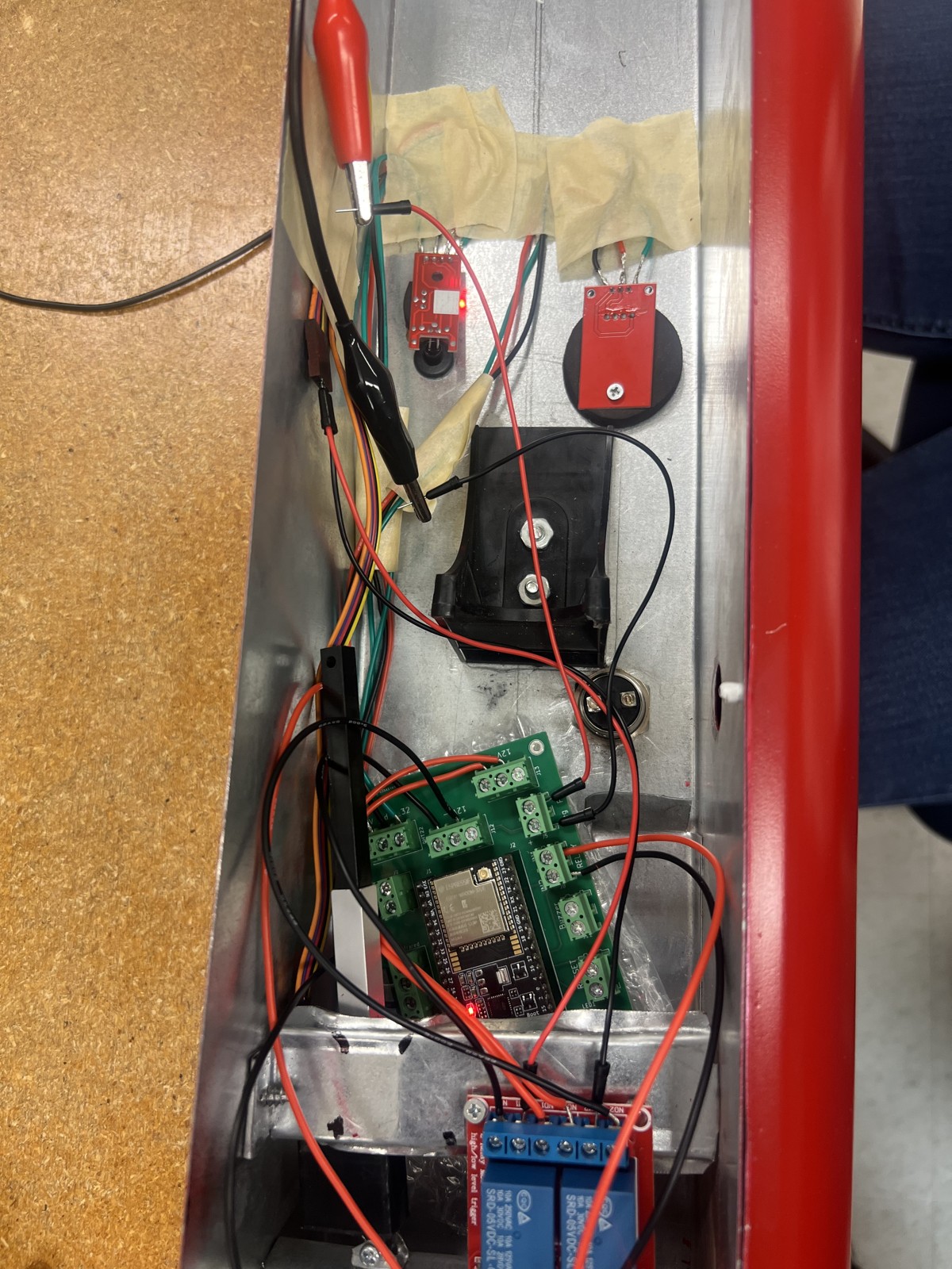
Actuator control: A relay controlled the 12V actuator that pressed the extinguisher handle. Firmware limited activation to approximately five seconds to reduce mechanical stress and actuator overuse.
Recovery: Automatic Wi-Fi reconnection and reset behavior helped the prototype return to monitoring after an event.
04 / TESTING & RESULTS
Evidence from acceptance testing.
The team used inspection, demonstration, output analysis, and repeated hardware trials in a controlled indoor environment. Results below are reported in Section 6 of the final project report.
| Measure | Reported result | Context |
|---|---|---|
| Fire detection | All 6 trials under 2 seconds; average ≈ 1.48 seconds | Flame-source trials with the physical prototype |
| Suppression activation | Within the 3-second target | Actuator deployment and retraction verified during tests |
| Remote notification | SMS delivered within the 5-second target | Twilio alerts reported successful in all tested cases; a separate SMS trial count is not specified |
| Standby operation | At least 24 hours | Continuous standby operation in the test setup |
| Requirements | 17 active requirements verified, no failures | 20 originally defined; 3 removed from scope. The report rates 15 as exceeding expectations. |
Source: team Final Project Report, “Results and Acceptance Testing” and requirements verification matrix. The measurements reflect the controlled prototype tests.
DESIGN DOCUMENTATION
Engineering evidence
Visuals from our final senior design presentation connect the prototype to its design and verification work. Select a diagram to inspect the full-size image.
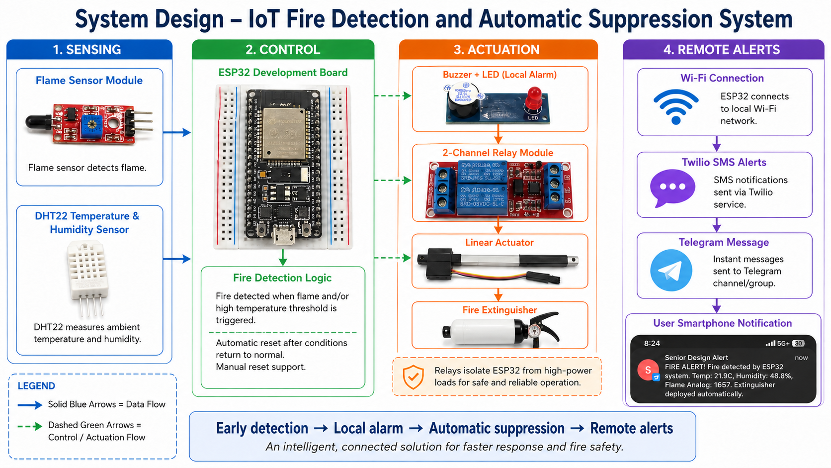
Adapted team presentation diagram showing sensing, ESP32 control, actuation, and remote notifications. The extinguisher illustration and label have been updated.
Team final presentation · Slide 5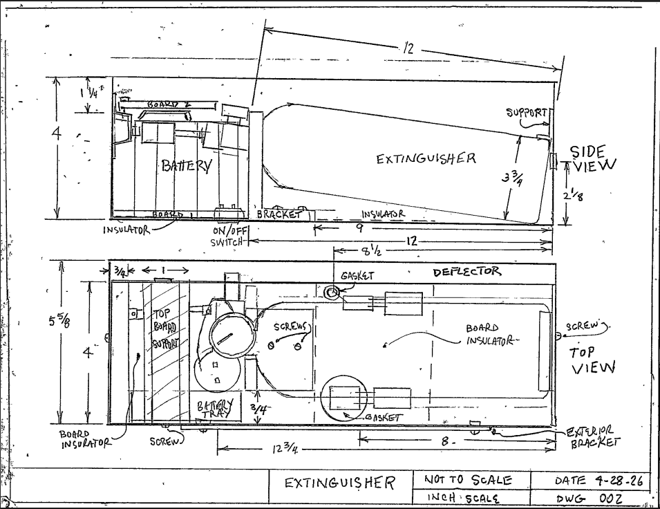
Side and top sketches showing the planned placement of the extinguisher, actuator, battery, and control hardware.
Team final presentation · Slide 7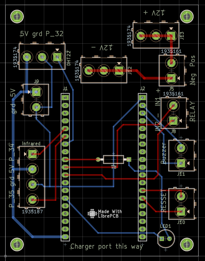
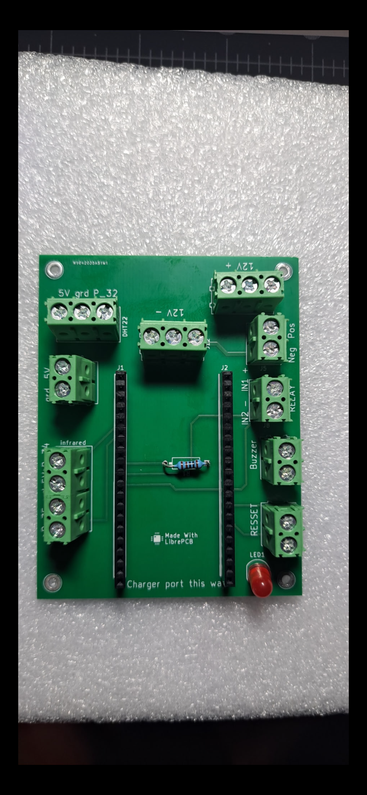
Board layout showing component positions, terminals, and routed connections.
Team final presentation · Slide 10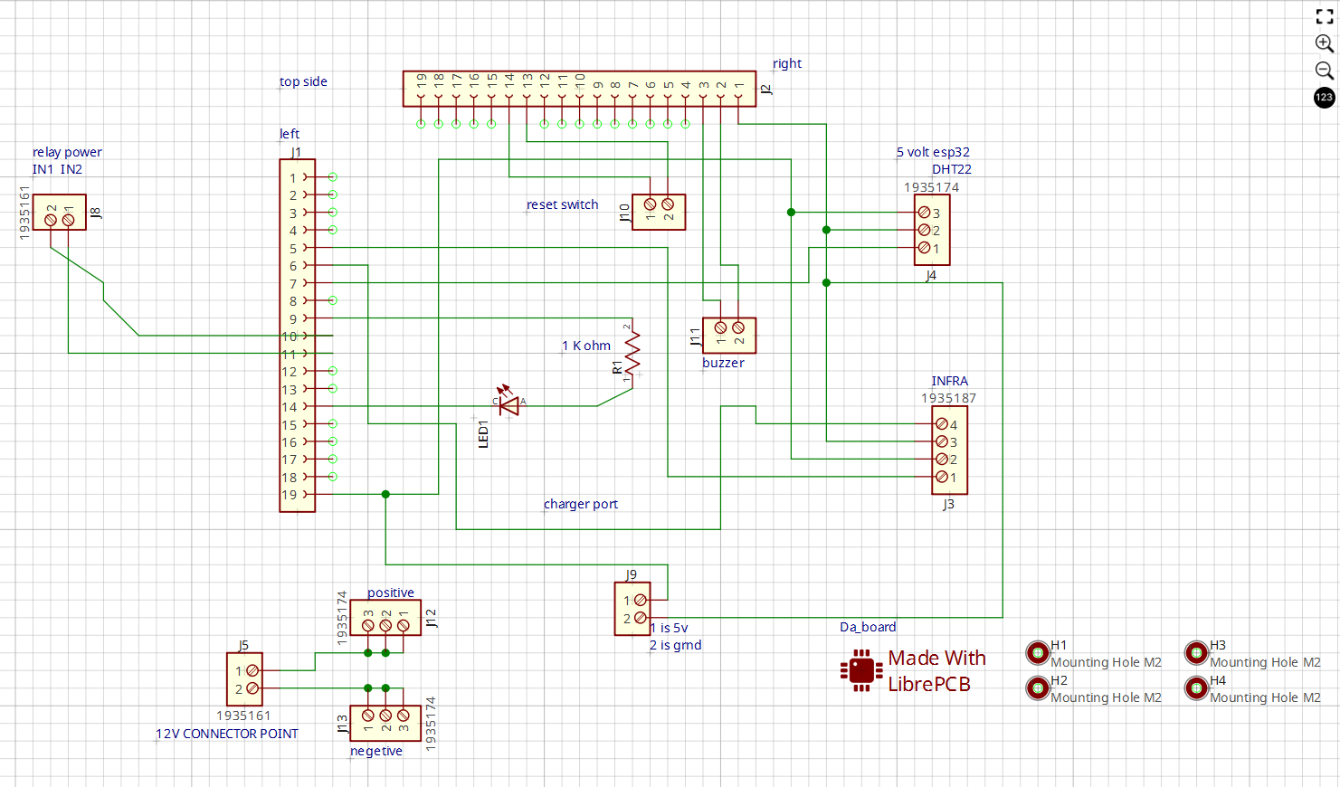
Circuit connections for the controller and the connected sensor and response hardware.
Team final presentation · Slide 11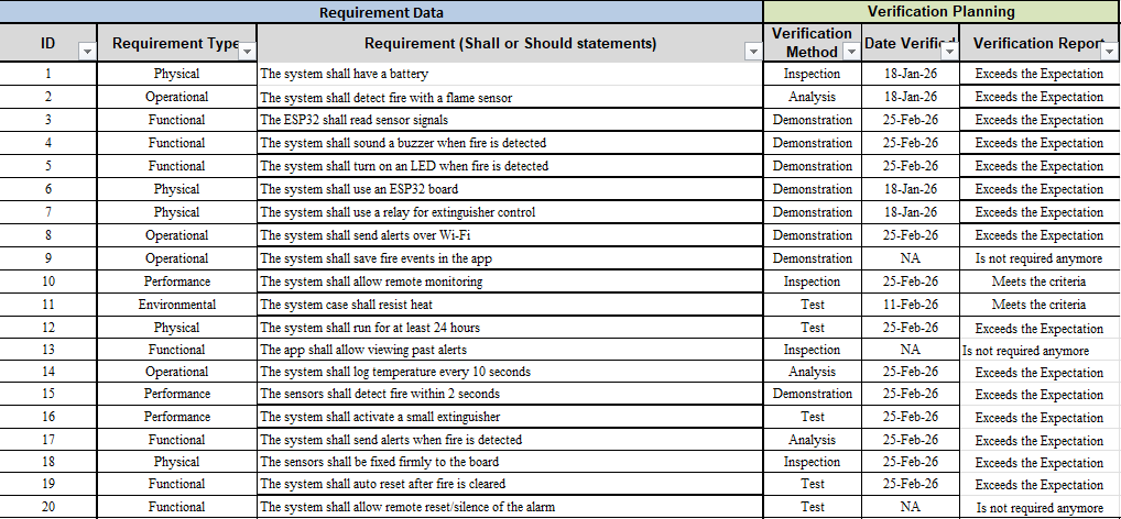
The team tracked verification methods and outcomes against the original requirements. Seventeen remained active; three were removed from scope.
Team final presentation · Slide 17PROJECT RISK ASSESSMENT
Probability and impact
The team recorded 20 project risks and rated probability and impact from 1 (very low) to 5 (very high). This matrix plots the values in the presentation’s risk register, with a score of probability × impact.
| Probability / Impact | 1 · Very low | 2 · Low | 3 · Medium | 4 · High | 5 · Very high |
|---|---|---|---|---|---|
| 5 · Very high | —Score 5 | —Score 10 | —Score 15 | —Score 20 | —Score 25 |
| 4 · High | —Score 4 | —Score 8 | —Score 12 | —Score 16 | R20Score 20 |
| 3 · Medium | —Score 3 | —Score 6 | R2, R9, R12, R14, R19Score 9 | R1, R5, R6Score 12 | R11, R15Score 15 |
| 2 · Low | —Score 2 | R17Score 4 | R7, R16Score 6 | R13, R18Score 8 | R3, R4, R10Score 10 |
| 1 · Very low | —Score 1 | —Score 2 | —Score 3 | —Score 4 | R8Score 5 |
Replotted from the numerical register on slide 20 because some placements in the original heatmap differ from that register. These are planning ratings, not measured failure rates or residual risk after mitigation. The register includes concepts such as MQTT and an app that were later removed from the implementation scope.
Risk descriptions and ratings
| Risk | Description | Probability | Impact | Score |
|---|---|---|---|---|
| R1 | Wi-Fi connection failure | 3 | 4 | 12 |
| R2 | False flame readings from environmental noise | 3 | 3 | 9 |
| R3 | Temperature sensor malfunction | 2 | 5 | 10 |
| R4 | Relay fails to activate extinguisher | 2 | 5 | 10 |
| R5 | Power supply interruption | 3 | 4 | 12 |
| R6 | Software bugs cause missed or false alarms | 3 | 4 | 12 |
| R7 | MQTT server downtime | 2 | 3 | 6 |
| R8 | Extinguisher empty or fails to discharge | 1 | 5 | 5 |
| R9 | App alert display failure | 3 | 3 | 9 |
| R10 | Safety hazard during live-fire testing | 2 | 5 | 10 |
| R11 | Overheating or short circuit | 3 | 5 | 15 |
| R12 | Component compatibility issues | 3 | 3 | 9 |
| R13 | Relay driver circuit failure | 2 | 4 | 8 |
| R14 | Corrosion or environmental wear | 3 | 3 | 9 |
| R15 | Memory overflow or stack crash | 3 | 5 | 15 |
| R16 | OTA update failure | 2 | 3 | 6 |
| R17 | Time synchronization errors | 2 | 2 | 4 |
| R18 | Wi-Fi credential exposure or hacking | 2 | 4 | 8 |
| R19 | Data loss during transmission | 3 | 3 | 9 |
| R20 | Insufficient calibration or testing | 4 | 5 | 20 |
IOT SENIOR DESIGN / FROM BUILD TO RESPONSE
Inside the project
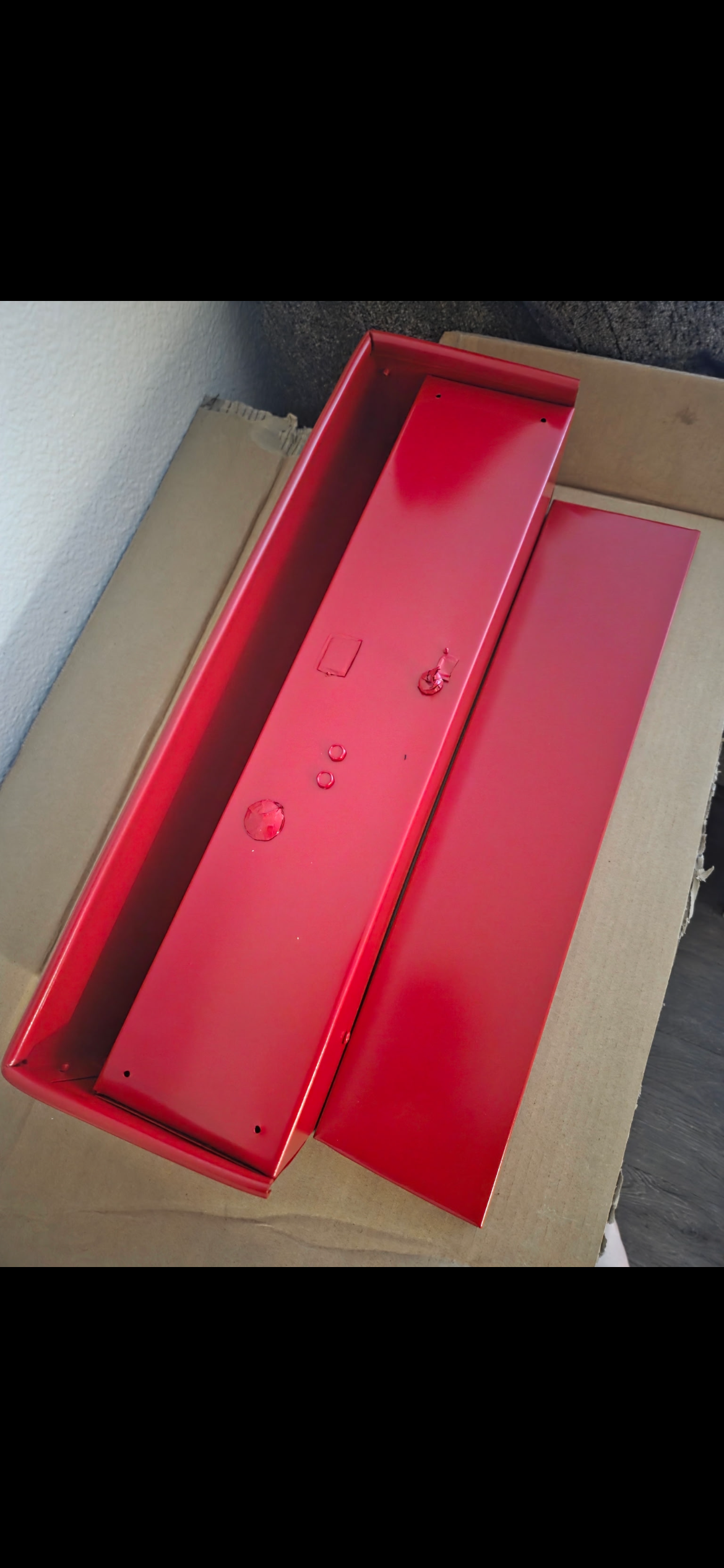
Hardware, assembly, and notifications from our senior design system. Select an image to see the full-size view.
05 / TRADEOFFS & NEXT STEPS
What I would carry forward.
The final prototype cost was $366.38 against an initial $250 target—a $116.38 overrun. The actuator, fabricated PCB, shipping, and integration costs made the gap between a parts estimate and a complete prototype clear.
The project reinforced the value of testing subsystems before integration and tracing results back to requirements. For a next iteration, I would prioritize false-alarm testing under varied light conditions, long-term actuator reliability, additional smoke or gas sensing, and power failover.
For cybersecurity, the connection is practical: validate input signals, make system behavior observable, and plan how a system recovers when something goes wrong.